What is dredge
A dredge is a mechanism for separating gold from the soil. Nowadays, it occupies a leading position among both individual and industrial gold miners as a means for washing precious metal. The reason for this lies in the simplicity of the design and at the same time the high performance of the dredge.
Features of the dredge
Not every deposit is suitable for gold dredging. Gold miners should take into account the following features:
- Healing gold is only possible in bodies of water: rivers, seas, etc. The dredge device is to blame (which we will look at in more detail below). The fact is that in water, rock particles weigh several times lower than in air. Accordingly, much less energy is required to lift them from the depths of rivers. When mining in open areas, it is necessary to significantly increase the power of the pump and electric motor, which is not practical due to the significant increase in the size and weight of the dredge.
- The need to conduct a study by geological services of the area for the presence of gold ore. The dredge itself does not have sensors and mechanisms for searching for gold. Its function is only to separate the metal from the ground. It is worth noting that today a deposit is considered profitable from a financial point of view if there are 3 grams of gold per 1 ton of rock.
- Not all types of soil are suitable for gold dredging. This refers more to the size of rock particles, rather than their chemical composition. The reason for this is the limitation in the size of the suction hoses through which soil is drawn from the bottom of reservoirs.
Parts for making dredges
A self-made dredge may be of interest not only to prospectors, but also to engineers. The mini-dredge for gold mining has a fairly simple design. The main material for creating a machine is either aluminum or plastic. Moreover, car tires or plastic barrels must be attached to the frame of the device for buoyancy. The device also includes:
- Engine.
- Water pump.
- Compressor.
- Hoses, their ideal diameter is 10-12 centimeters, which regulate the load.
- A trench for washing the soil, you need to make it yourself. The inside of such a trench is covered with special diligent moss, in which grains of gold are retained. It is made of steel and also has an aluminum gateway attached to it.
Don't forget about the valve, without which the dredge will break. It protects the pump from sand from the wash water. You can check the dredge using marked lead, which is thrown into a regular body of water. If, as a result, almost all the lead is returned to the owner of the mini-dredge, it means that the device is working.
Using a mini dredge can be dangerous and illegal. But many risk their reputation and lives in the hope of finding gold and getting rich. The effectiveness of using even a smaller copy of a special machine has been proven and therefore more and more craftsmen are trying to design this device.
Dredge device
As mentioned earlier, the design of the dredge is not complicated.
Minimum electrics, maximum parts from a regular technical store. So, the following components of the dredge are distinguished:
- Suction tip. In appearance it looks like a tapering cone. Made from thin sheet steel no more than 2 mm thick. The edges of the tip are fastened by manual arc welding. Different diameters of the cone bases are necessary to increase the suction area on the one hand, and on the other to more quickly transport soil to the surface of the water.
- Supply hose. As a rule, it is represented by a high-pressure hose with a diameter of at least 12 centimeters. This size is due to the weight limitation of the dredge. To increase the rigidity and strength of the hose, a metal frame is embedded into its base.
- Pressure hose. The same sleeve, but with a diameter of 50 millimeters. The main purpose of this unit is to supply clean water for washing and transporting gold with soil.
- Pump. Provides direct pressure for supplying rinsing water. Not every pump is suitable for this. The most important parameter here is maintaining operability when large soil particles enter the working cavity. Various types of diaphragm, vane and gear pumps have proven themselves to be the best.
- Electric motor. Necessary for transmitting torque to the pump. Typically, asynchronous three-phase motors are used, as they are the most convenient to operate. Their power depends on the performance of the installation. For a small-sized dredge, 2 hp is enough.
- Flushing sluice. It is a curved container. The gateway serves as a place for screening gold particles from rocks. It is made from thin-sheet materials: steel and aluminum, in the case of a lightweight design.
- Gutter A vessel where the deposited gold is directly collected.
- Source of electricity. Required to supply electric current to the motor. This can be either a battery or a gasoline generator. In the case of large industrial scale mining, a power line is connected to the dredge.
- Floating platform. Serves as a frame for installing all of the above equipment. Another function of the platform is to maintain the buoyancy of the dredge on the surface of the reservoir. Stability afloat is maintained by large tanks filled with air. The platform is made from structural materials. Most often this is aluminum.
Steps before using dredge
To understand the profitability of a business, you should familiarize yourself with the statistics. Explored sources of gold will consistently generate income for 2-3 years, and illegally explored placers will bring profit for the next decade. Although engaging in such activities, much less using mini-drags, is prohibited by law.
Before using the devices, it is worth carrying out the following steps in preparation for production:
- Exploration of the boundaries of the deposit, marking them on the map.
- Calculations and analysis of the approximate gold content in soil or water.
- The acquisition or lease of land on which the mines are located is the stage that officially allows gold mining. Sometimes industrial companies sell licenses to private entrepreneurs, and they can use the territory for their own search. This method is the easiest, since it is known for sure that there is gold in the area.
- If exploration was carried out independently and the land has already been purchased, before using dredges it is worth building a mine, or in some cases digging a quarry.
The extraction of precious metals in industry is carried out in several ways. One of them is called hydraulic. It is based on extracting metal and separating it from impurities using high water pressure. But now the priority is to use the second method using a dredge to wash gold.
Principle of operation
Gold ore particles are purified from rock in several stages:
- The electric motor turns on and the pump directs water into the pressure hose, thereby discharging the space between the river water and the suction tip.
- Due to the vacuum formed, the soil is drawn in by the suction nozzle and moves along the supply hose to the flushing sluice.
- Once there, the soil and water pass through a certain system of drops. The goal here is to separate the denser gold from the lighter rock particles.
- Then, after a certain time, the gold settles in the gutter, and the remaining soil is removed into the river along with the flushing water.
Before the actual start of the washing process, the dredge is adjusted to ensure the accuracy of catching the precious metal. This is done by adjusting the overflow differential, flow and pressure of the pump.
To ensure greater reliability of the correct operation of the dredge, a preliminary check is carried out, which consists of passing pieces of lead marked with paint through it. If, after passing through the sluice gate, painted metal is observed in the chute, then the dredge is working properly. If not, then it is sent for revision.
Operating principle of the dredge
Dredge equipment, regardless of whether it is a pump or a bucket, is designed for one purpose - the extraction of ore containing valuable minerals and its transportation to the destination, that is, to the place where the mined material is either processed or immediately washed (as in the case with gold).
For example, a bucket dredge most often simply dumps the mined conglomerate into a heap, but a floating pumping station immediately washes and collects pure gold, throwing unnecessary debris to the bottom. But the principle is the same - extract, transport and sift.
Classification of dredges
There are many types of gold dredges. They are divided according to the following parameters:
1. Power. This refers to the depth from which the dredge can remove soil. Typically, this value ranges from 5-50 meters.
2. Portability. There are stationary and floating dredges.
2.1. Stationary ones are powerful industrial dredges weighing up to 1,500 kg. In terms of their dimensions, they are comparable to 4-story modern houses. They have a large number of electronics and have greater ability to regulate the gold mining process. The management staff of such dredges consists of at least 10 people.
2.2. Floating – more mobile dredge models. They are significantly less in weight (40-150 kg) and power. Even 1 person can handle this dredge.
3. Screening performance. Depending on the type of pump, the diameter of the hoses and the type of flushing sluice, it can vary from 100 to 1000 kg of soil per hour.
Dredging business (dredging)
Details Category:
DRAGING CASE
,
dredging
(dredging) is a mechanized method of developing placer deposits of gold, platinum and other minerals using special mechanisms - dredging.
Description of the dredge
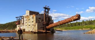
. A dredge is a floating dredging machine equipped with devices for washing the excavated soil.
A general view of the dredge during operation is shown in the figure, and a schematic longitudinal section and plan of the dredge are shown in Fig. 1 and 2. Here 1 is a pontoon on which all the dredge devices are located, 2 is a scoop frame mounted on the central mast 3 and carrying the lower drum 4 at the lower end; the frame can rise and fall, rotating about an axis passing through the eyes of the upper end of the frame; the lower end of the frame is suspended on ropes to the front mast 5.
A chain of scoops runs around the scoop frame, going around the lower and upper 6 drums; the latter is the leading one and rests on the central mast.
The placer material raised by the scoops (sand, gravel, clay, boulders) falls out of the scoops as they go around the upper drum and through the filling hatch 7 enters the washing barrel 8, which is a drum screen. Here, as the barrel rotates, the material is separated: a small part of it falls through the holes of the barrel and flows first to the transverse and then to the longitudinal sluices 9, which are low gutters of rectangular cross-section, equipped with devices for catching precious metal.
The sluices are installed on two sides, and on large dredges they are built on two levels, as shown in Fig. 1; right and left, upper and lower locks are unloaded into decks 10, which take the material behind the stern of the dredge. Large material - pebbles and boulders - are unloaded at the lower end of the barrel and rolled down a chute 11 to the lower end of the elevator, which in most cases is a belt conveyor mounted on the elevator frame 12; this frame is suspended from the rear mast 13. During operation, the dredge moves using ropes or ropes and piles 14; the piles are suspended from the rear mast. In addition to the indicated parts, the following are installed on the pontoon: winches 15, with drums for ropes that move the dredge and raise and lower frames and piles; centrifugal pumps 16, supplying water to the filling hatch, barrel and sluices; motors 17 driving the dredge mechanisms. For ease of installation and repair, movable hoists and lifts 18 are installed. Dredge control is concentrated in the pilot's booth 19.
Scheme of work
. During operation, the dredge floats on a lake or river, at the bottom of which the mined metal-bearing sediments lie, or in a specially constructed reservoir - a dredge pond. The dredge produces a placer in front of itself, unloading the washed products into a dump formed behind the stern of the dredge. Depending on the method of movement of the dredge, the shape of the face and the path of the dredge are different; if the forward movement of the dredge is carried out using a rope, then the operating diagram takes the form shown in Fig. 3;
here 1 - front side ropes, 2 - rear side ropes, 3 - head rope, the tension of which is achieved by pressing the scooping chain onto the face. During operation, the dredge moves from one side of the pond to the other, describing an arc of a circle, the center of which is at the point where the head rope is secured. When a dredge operates on piles, the dredge rotates around one of the two piles, and is driven by one of the side ropes; in the diagram (Fig. 4) the solid line shows the extreme left position of the dredge; from this position, the dredge, rotating on pile 1, moves to the extreme right position (linear dotted line); then pile 1 rises, pile 2 lowers, and the dredge moves in the opposite direction, again to its leftmost position (dotted line).
However, this position is not identical with the previous one; during the rotation around the piles, the dredge managed to move forward a certain distance, called the dredge pitch; the size of this step depends on the distance between the piles and the angle of rotation of the dredge. Depending on the nature of the metal-enriched layer, the dredge either immediately produces the entire thickness of sediment and even part of the raft (loose collapsing sediment) or selects this thickness layer by layer (dense clay sediment), for which it is necessary to lift the scooping frame from its lowest limit position to the appropriate height.
Design of individual dredge parts
. The most important part of the dredge is the wooden or metal (steel) pontoon. A metal pontoon is lighter than a wooden one (approximately 40%), which results in a lower draft of the dredge; it has a longer service life (15 or more years, while wooden pontoons last 8-10 years), is fire safe and requires less repairs. However, the initial costs for installing a metal pontoon are higher, especially for long-distance transportation to the place of work, and when the roads are in poor condition. In this case, it is more profitable to build a pontoon on site, if, of course, there is a forest suitable for construction nearby. The construction of a wooden pontoon requires high-grade dry forest materials and precise workmanship. A general view of the pontoon is shown in Fig. 5.
The pontoon has a cutout in the front part for the passage of the scooping apparatus; the outer corners of the pontoon in the front part are beveled or rounded in order to more fully develop the corner parts of the dredge pond; in some cases (with a small digging depth), the bottom of the pontoon in the aft part (sometimes in the front part) is beveled at a certain angle to the horizontal plane, so that the material unloaded from the locks, forming a dump at the bottom of the dredge pond, does not interfere with the free maneuvering of the dredge. Pontoon d.b. particularly rigid structure, both longitudinally and transversely. This is achieved by a large number of strong connections between parts of the pontoon frame.
The main structural elements of a metal pontoon are (Fig. 6) frames, consisting of floors 1 and side branches 2, connected at the joints by briquettes 3; the frames are located along the length of the pontoon at a certain distance and are sheathed on the outside with steel sheets. The side branches of the frame are connected from above to beams 4 using brackets 5; the floras of the frames are connected to the beams by vertical pillars 10. To give the pontoon greater rigidity in the transverse direction, braces are sometimes installed 6. The rigidity of the pontoon in the longitudinal direction is achieved by the outer skin, deck and internal walls, which serve as a continuation of the cutout walls, as well as stringers 7 and carlings 8. In large dredges, additional stringers 9 are also installed, and sometimes keelsons 9′ are laid along the pontoon.
The shape and size of steel grades (angular, box, tee, etc.) are selected depending on the size of the dredge and the distribution of the load, which ch. arr. coincides with the places where the masts are strengthened. Much attention is paid to the method of articulation of the masts with the frame of the pontoon and the proper connection between the masts, which also increases the strength of the pontoon in the longitudinal direction. Masts are made of wood and metal. The most dangerous place in the pontoon is its front part at the cutout; therefore, the walls of the cutout and bow are made of thicker sheets; in addition, the pontoon is divided by waterproof partitions into several isolated parts. The dimensions of the pontoon depend on the power of the dredge installation, as well as on the dredging depth; the ratio of the length of the pontoon to its width is from 2.5 to 3.
The dredge scooping apparatus consists of a scoop frame, drums and scoops. The scoop frame is a riveted beam, the length of which depends on the depth of scooping. At the upper end the frame has holes for the passage of an axle by which the frame is suspended from the central frame or to the shaft of the upper drum, and at the lower end there are projections that carry bearings for the axle of the lower drum. On the upper surface of the frame there are rollers along which the scoops move.
The figure shows the dredge in the process of assembly: the scoop frame has not yet been raised, but the rollers on it have already been strengthened. The chain of scoops bends around steel drums as it moves. The lower drum has a hexagonal (Fig. 7) and sometimes round shape.
It is equipped with flanges to prevent the scoop chain from jumping off. The edges of both drums are equipped with replaceable manganese steel linings. The picture shows the lower end of the frame, the lower drum and part of the scoop chain.
The bearings of the lower drum axles and rollers are carefully sealed. The upper, driving drum (fig.) is secured on the shaft with keys and is equipped with mounting rings to avoid lateral movement. The number of faces is usually 6.
Particular attention is paid to the strength of the axis of the upper drum, since it is subjected to strong and uneven stresses; its diameter in large modern dredges reaches up to 0.5 m. Scoops directly perform the work of scooping soil, and therefore the shape of the scoop in each individual case is determined by the nature of the soil. Scoops and especially their cutting edges (lips) are made from the best grades of special steels (chromium-nickel, manganese). The wall thickness is from 6 to 10 mm, and the lip thickness is up to 30 mm; the weight of the scoop of large dredges reaches 2.5 tons. The scoop consists of two or three parts; bottom with two eyes in front and a protrusion at the back, scoop bodies and lips. Very important for the smooth operation of the dredge is the strength of the connection of the scoops into one endless chain. Depending on the method of connection, the result is: 1) a continuous chain of scoops, when the scoops follow directly one after the other (used primarily in so-called American-type dredges) or 2) an intermittent chain, when the scoops follow one after another with an interval of one scoop ( used mainly in dredges, the so-called New Zealand type). The number of scoops fed by an American-type dredge per minute is 19-22, and by a New Zealand-type dredge 12-13. A continuous chain of scoops ensures quieter operation of the dredge (less strong shocks), but if there are large boulders in the scattering, the scoops wear out faster: it happens that their bottoms are pressed through by the boulders located in the underlying scoop at the moment when the scoops, having gone around the lower drum, are located in a straight line. Connecting bolts are made from the best grades of steel: Juba Construction C°, for example, makes them from forged chromium-nickel steel, specially hardened in oil. The diameters of the bolts in large dredges reach 0.2 m.
The washing devices on the dredge are the barrel and the sluices. The material extracted with scoops, passing through the grate (to remove large boulders) and the filling hatch, is sent to the barrel. The purpose of the barrel is to bring the material into a sufficiently loosened state, separate boulders and large pebbles and send material containing grains with a diameter of no larger than 18 mm to the sluices. Dredges use almost exclusively hollow cylindrical barrels with a diameter of up to 3 m and a length of up to 17 m; The tilt angle of the barrels is about 4°. The general view of the barrel is shown in the figure.
The side surfaces of the barrels consist of perforated sheets of boiler iron riveted to the frame, usually with round holes increasing from the upper end to the lower with a diameter of 8 to 18 mm. The barrel is driven into rotation by one or two friction rollers; In addition to the rollers supporting the barrel, thrust rollers are also installed to prevent the barrel from sliding in the direction of the slope. The water required during the process of wiping the material is delivered to the barrel under pressure through a special pipe. The lower part of the barrel is enclosed in a casing, under which there is a distributor. The purpose of the latter is to evenly distribute the material sifted through the holes of the barrel on both sides of the sluices. A schematic representation of the position of the barrel, casing and sluices is shown in Fig. 9:
here 1 is a barrel; 2 - water supply pipe; 3 - material to be wiped; 4 - casing; 5 — upper tier of locks; 6 - lower tier of locks, 7 - auxiliary locks, directing part of the material that has fallen from the upper locks to the lower locks; 8 - water from the nozzles of the water supply pipe, supplied under pressure.
Sluices are devices whose purpose is to catch grains of gold released from their mechanical mixture with sand and clay. Sluices are narrow (0.6–0.9 m) gutters, often metal, installed with a slope (0.100–0.125) and equipped with stencils for catching gold grains (see Hydraulic developments). From the distributor, the material flows first to the transverse sluices, and then to the longitudinal ones. The area of the sluices can vary greatly, and in the newest dredges there is already a noticeable tendency towards a steady increase in the ratio of the area of the sluices to the volume of the washed rock: for this purpose, the sluices are also located on the sides of the pontoon on brackets. On dredges with a scoop capacity of less than 8 ft.3 there is up to 250 ft.2 of lock surface per 1 ft.3 of scoop capacity. With a larger scoop capacity, two-tier sluices are installed. The washed material is unloaded at some distance behind the pontoon, and large debris (pebbles, boulders) is transported to the dump using belt or box elevators. In the newest dredges, two, sometimes even three elevators are installed.
The piles around which the dredge rotates during operation are riveted iron or wooden (4 beams) beams; they move in special guides - pile holders, located at the aft part of the pontoon, and are lifted by metal ropes using blocks mounted on the rear mast. The lower part of the pile is equipped with a cast steel shoe, with which it crashes into the bottom of the reservoir. The weight of large dredge piles reaches 60 tons.
The pumps supplying water to the barrel operate under a pressure of about 4 atm; the remaining pumps supply water to the locks, loading hatch and some other devices. The water consumption of dredge devices is large and in volume is equal on average to ten times the amount of washed rock.
Types and conditions of use of dredges
. In addition to the described type (stacker dredges), other types are found, although rare:
a) suction dredges, in which material is extracted using a powerful centrifugal pump that sucks metal-bearing material from the bottom of the reservoir;
b) single-bucket dredges, the scooping apparatus of which is a steam shovel mounted on a pontoon, and
c) tong dredges, in which the lifting of metal-bearing material is carried out by a device similar to the corresponding part of a tong-type rope excavator.
The use of dredges has significantly increased the number of developed placer gold deposits. For example, in 1927 in Alaska, where 34 dredges operated, 52% of alluvial gold was mined by this method. The use of the dredge mining method requires the presence of certain technical and economic prerequisites, namely: 1) the placer should not lie deep (for example, the powerful 17-foot dredge installed at the Lena mines and designed for a digging depth of 24 m is one of the deepest working dredges); 2) if the placer is not located at the bottom of water basins, then it should be possible to construct a dredge pond; 3) the placer must contain a sufficient amount of precious metal and not be replete with large boulders larger than the size of the scoops; 4) raft d.b. “drilling”, i.e. succumb to the destructive action of scoops, because otherwise a significant part of the metal will be lost (usually, during dredging, up to 20% of the metal contained in the placer is lost); 5) the placer must contain sufficient reserves of material to be processed, providing at least a 10-year depreciation period.
Dredging performance and cost
. The theoretical performance of a dredge is determined by the number of scoops fed per unit time, their capacity and the degree of their filling. The dredges get their definitions based on the capacity of the scoops (in ft.3): three-foot, seventeen-foot, etc. Longridge, based on numerous observations of the work of New Zealand dredges, gives limits for the degree of filling of the scoops to 50.2% and 65.8%, on average - 57%; According to American practice, the degree of filling of scoops under favorable conditions (loose sediment, loose thigh, high face) rose to 85-87%, while with rocky soil it dropped below 33%. In addition, the experience of the person directly managing the dredge operation has a significant influence on the degree of filling. The hourly productivity of American dredges in California, according to Janin, is expressed in the following figures.
The length of the working season depends on the climatic characteristics of the area; Thus, for Californian drags, the number of working days per year when work is possible is normally 363-364; in Alaska this number for dredges of medium power and shallow scooping ranges from 120-150 days; for the Urals and most of Siberia the duration of the working season may be. accepted for powerful drags at 7 months.
The choice of dredge type in terms of its performance is influenced by the following factors: the supply of sand, the presence of large stones in the placer (a large scoop capacity is required) and the dredge delivery conditions. On bad roads, delivering a dredge to a place sometimes costs more than the dredge itself; Thus, a 17-foot dredge from the Bucyrus plant, installed on the Bodaibo River in the Lensko-Vitimsky district, cost 920,000 rubles at the plant, and its delivery cost over 1 million rubles.
The cost of dredge development, expressed in kopecks. per 1 m3 of processed material, varies within very wide limits depending on the nature and size of the placer, the number and size of dredges, the duration of the working season, the cost of labor, materials and energy and the amount of depreciation. According to Cleveland data dating back to 1927, 132 dredges operating in California over the past 28 years and processing about 760 million m3 showed an average cost of 1 m3 of 17.6 kopecks. The cost of dredging for individual expense items as a percentage of the total cost is expressed by the following figures:
An example of the high cost of work is dredge development in Alaska (Yukon Gold С°); here the cost of 1 m3 ranged from 50.8 to 89.0 kopecks. and higher for individual dredges operating in unfavorable conditions; The reasons for the high operating cost of 1 m3 for Alaskan dredging are: 1) short working period, 2) expensive labor and materials, and 3) the prevalence of permafrost (the cost of artificial thawing of this permafrost accounted for over 50% of the total cost of dredging). For medium-power dredges (5-7.5 feet), operating within the USSR, the cost of 1 m3 ranged from 16.0 to 22.4 kopecks for the Urals and from 21.0 to 28.5 kopecks for the Yenisei taiga. (according to the commission at the “Advisory Office of Gold and Platinum Miners”).
The working and maintenance personnel on the dredge are small, since all production processes, with the exception of rinsing, are mechanized. At the large electric dredges in California, the team consists of 11 people: one dredge manager, three dredgers, three oilers and four auxiliary workers, one of whom is a blacksmith. An illustration of the degree of mechanization of the entire process is the number of man-days per 1 m3 of material extracted by dredging: for the best Ural dredges it is 0.003-0.025, and for Californian ones - 0.005-0.010; when developing placers with muscular labor (Kariyskie mines in Altai) up to 0.5 is required. Energy consumption depends on ch. arr. on the depth of excavation and, especially on the nature of the placer material and ranges from 1.0 to 1.5 kWh, reaching in special cases 3.1 kWh per 1 m3. When developing a placer deposit with one dredge, it is advantageous to install a steam dredge; when two or more dredges are operating simultaneously or if there is an electric power station in the area, the installation of electric dredges seems more rational.
A major item in the cost of dredging is the materials consumed in repairing the dredge, which is explained by both the large weight of the metal consumed and its high cost (special steels).
The importance of dredging in the development of alluvial gold deposits is very great: huge gold-bearing areas, which were considered unprofitable before the introduction of this method, as well as developments abandoned due to the low content of precious metal in them, gained industrial importance and began to be developed.
Source: Martens. Technical encyclopedia. Volume 7 - 1929
- < Back
- Forward >
Other mining methods
Extraction of gold from rocks is done not only by dredging. It is also worth noting the following methods:
- Manual. A gold miner extracts gold using a regular tray, washing the soil in it with water. This method was simple, but had very low productivity.
- Ore. Extraction is carried out in onshore deposits using special high-tech equipment: excavators, drills, etc.
- Hydraulic. The dredge mining method we are considering also applies to this. Gold is obtained by eroding rocks.
Rate this article:
Rating: 0/5 — 0 votes
How to mine gold sand by dredging
The process of washing sand with a dredge:
- The soil, which potentially contains particles of precious metal, is placed in the receiving hole.
- The installation washes the soil, removing excess fractions from it. The latest models of profile equipment are equipped with an automatic flushing function for coarse rock, which eliminates the risk of damage to the device.
- The washed soil is fed into a drum, where it is wetted and crushed into smaller parts.
- The next stage is that the soil is sent to the enrichment sluice, and then the remaining raw materials, which are guaranteed to contain nothing valuable, are thrown back.
The functionality of the dredge for sand extraction provides the ability to make individual settings, in particular:
- intensity of rock cleaning;
- fuel consumption;
- drum rotation speed;
- cleaning method (depending on soil type).